Saturday, April 6, 2024

Why Prefix a Command in AutoCAD With a Hyphen?

You are probably all familiar with the XLIST command, one of the Express Tools available with Autodesk® AutoCAD® and its verticals (but may not be available in AutoCAD LT®). This post explains why you might want to prefix that command with a hyphen.

The XLIST command.

The XLIST command reports properties of a nested object, such as the layer and linetype of a polyline within a block or an xreference drawing. This command is useful in identifying the layer and xref hosting a specific object. The command launches a small dialog to display the query results, as shown in Figure 1. 

The Xref/Block Nested Object List dialog.
Figure 1: The Xref/Block Nested Object List dialog. 

Based on the layer value in the dialog, the object is a polyline in an xreference drawing named x00000_p-site on a layer named cs-esmt-line

NOTE: The vertical bar in the layer value separates the xreference name from the layer name.

In the previous example, the layer name is completely visible within the dialog. Since the dialog can't be resized, if the xref name + layer name is too long, it might extend past the edge of the dialog, as shown in Figure 2.

A layer property value that extends past the edge of the Xref/Block Nested object List dialog.
Figure 2: A layer property value that extends past the edge of the dialog. 

Hyphens to the rescue!

Some commands allow a hyphen as a prefix, and XLIST is one. With the hyphen prefix, the command outputs the query results in the command line instead of the dialog. The result of running the -XLIST command on the same object is shown in Figure 3.

The command line result of the -XLIST query.
Figure 3: The command line result of the -XLIST query.

The query results in the command line show the full xreference name and the full layer name. As a bonus feature, you can copy the layer value to the clipboard and paste it into the layer palette filter of another drawing.

More Examples?

Another example of when to add a hyphen prefix is with the PURGE command. By running the command with the hyphen prefix, you can access the option to purge registered applications (Regapps), as shown in Figure 4.

The command line options for the -PURGE command.
Figure 4: The command line options for the -PURGE command.

For Civil 3D® users, multiple commands can be run in multiple drawings by creating a script file and using the Autodesk Batch Save Utility. It does a lot more than just saving files! Using -LAYER you can create and modify layer properties directly from the command line. These commands can then be converted into programmable pieces for scripts or LISP routines.

  • (command "-LAYER" "ON" "G-ANNO-TTBL" "THAW" "G-ANNO-TTBL" "")
  • (command "-LAYER" "MAKE" "G-ANNO-SEAL" "")
Note that some commands, such as -LINETYPE, might begin in command line only mode, but once a dialog such as "file open" is launched, the command is no longer command-line only.  Details of that process will not be covered in this post.

I hope you find this information useful.

--TomR


Wednesday, December 26, 2018

Update to Set Working Folder Dialog

Set Working Folder Uses File Open Style Dialog

A new feature of Civil 3D 2019 is an update to the Set Working Folder dialog. Previously it was strictly a browse and select folder dialog. As of Civil 3D 2019, the Set Working Folder dialog now resembles a File Open dialog.


This may seem like something small but for those of you that must drill multiple folders deep to select the Working Folder for a project, this new dialog is a nice improvement because now you can copy then paste a folder path from the Windows Explorer address bar into the Set Working Folder dialog address bar or Folder path.

Monday, December 3, 2018

Convert Survey Figures to Polylines

Sometimes survey figures are exactly what you want and other times you just want a polyline at elevation zero. If your like me, you created a figure style that flattens all elevations to zero then you exploded it. If that figure had an arcs, they became segmented like this:
I'm happy to report that there is a workflow to create these polylines with arcs from figures. I have confirmed that this workflow will work for versions 2016 through 2019. Note that the polylines will not update if the survey figure changes and is updated in the drawing.

Create a 2D figure style in your template

  1. In your template, expand the Toolspace > Settings tab > Survey > Figures category.
  2. Right click on Figure Styles and choose New.


  3. In the Figure Style dialog > Information tab, set the figure style name to 2D.


  4. In the Figure Style dialog > 3D Geometry tab, set the Figure display mode to Flatten figure to elevation and confirm that the Flatten figure to elevation is set to 0.00.


  5. In the Figure Style dialog > Display tab, change the layer, color, linetype, and so on to meet your CAD standards then click OK.
  6. Right click on the Toolspace > Settings tab > Survey category and choose Edit Feature Settings.


  7. In the Edit Feature Settings - Survey dialog, expand the Default Styles category and set the Default Figure Style to the 2D figure style you just created then click OK.


  8. Save and close the template.

Export Survey Figures to Polylines at Elevation Zero

  1. Begin a drawing with the template that contains the 2D figure style.
  2. Open a survey database and import figures to the drawing. The default style should be the 2D figure style.
  3. Set the UCS to World then save the drawing.
  4. In the application menu, select Export > Export Civil 3D Drawing.


      NOTE: Exploding figures using the 2D figure style will create polylines with segmented curves. That's why you'll need to use the Export Civil 3D Drawing command to get polylines with arcs.

  5. In the Export Autodesk Civil 3D Drawing dialog, choose the folder for the exported drawing then click Export.


  6. When the export is complete, click OK in the Export Status Dialog then Cancel in the Autodesk Civil 3D Drawing dialog.


  7. Open the exported drawing and confirm that the figures were exported to polylines at elevation zero.
  8. Select all the polylines representing exported figures and copy to the clipboard with a basepoint using SHIFT+CTRL+C and entering 0,0 as the base point.
  9. If you are replacing the figures in the original drawing, you can now delete them.
  10. In the original drawing, confirm that the UCS is set to World then use CTRL+V and enter 0,0 as the insertion point to paste the polylines into the correct location.
  11. Save the drawing.
An alternate workflow might be to have a separate template for importing just figures into a temp drawing so that you can export them and they will be on the correct layer. For this you'll need separate figure styles for each type of figure/layer combination you need. Then you can choose to import figures into the original base drawing onto the feature line or equivalent layer and have them displayed as a 3d object instead of a 2D object.

Monday, November 19, 2018

Set Your Site...On Feature Lines

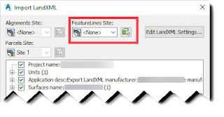
When importing LandXML files into Civil 3D 2019, there's a new setting for Feature Lines:

Use this setting to select a site for the Feature Lines you are importing. You can select a site from the dropdown list or use the green pic icon to select a site in the drawing.

You can also assign a site independently for Alignments and Parcels if any exist in the LandXML file that is being imported.

Tuesday, June 26, 2018

A360 Desktop Retired

In case you didn't see the A360 Desktop Retirement - June 19th, 2018 post in May, 2018, you may not know why you are seeing an Autodesk software CER appear on your screen at startup.


What this means to you is that the content will still be in both locations, but content in your online A360 Drive account will no longer be synchronized with content in your local A360 Desktop folder.

Uninstall instructions for A360 Desktop can be found here:

How to remove A360 Desktop
https://knowledge.autodesk.com/support/autocad/learn-explore/caas/sfdcarticles/sfdcarticles/How-to-prevent-installation-of-Autodesk-360.html

If you're looking for a replacement for the A360 Desktop synchronization on your desktop there is some useful information about the difference between A360 Drive, A360, BIM360, and Fustion Team here:

HELP: The difference between A360 Drive and A360, BIM360 & Fusion Team
https://forums.autodesk.com/t5/a360-tips-tricks-tutorials/help-the-difference-between-a360-drive-and-a360-bim360-amp/td-p/6351698